
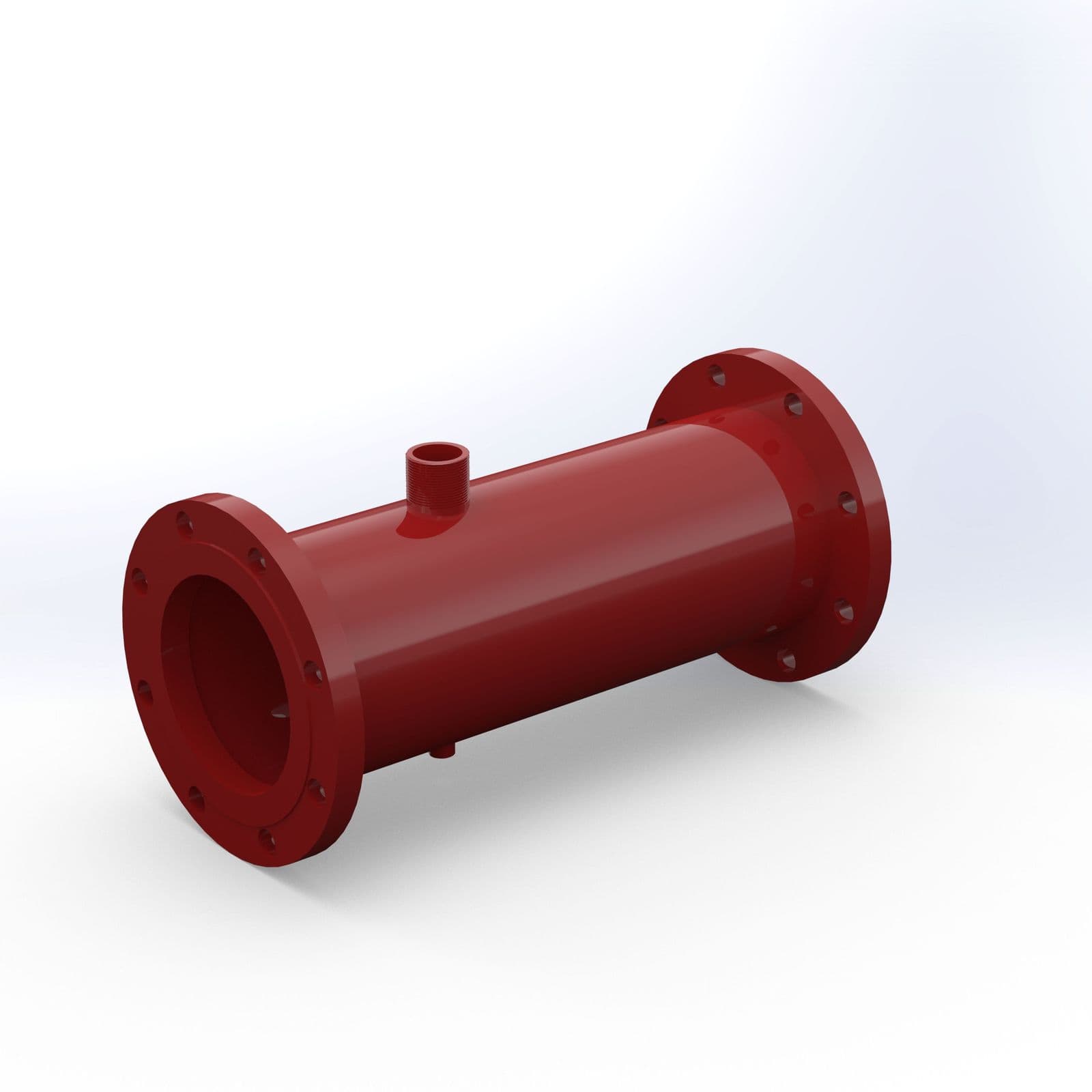
Foam Inductor
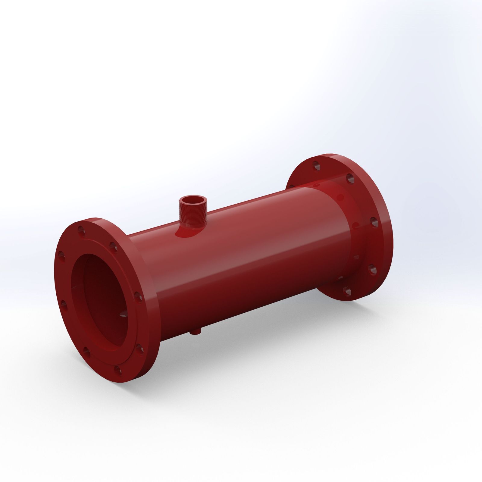
A fixed inline inductor that proportions foam concentrate into the water stream in constant-flow applications — a simple and reliable method for fixed installations.
At a glance
- Working pressure
- 6.5 to 12 kg/cm²
- Induction
- 3% or 6%
- Size
- 50 to 200 NB
- Back pressure
- 65% of inlet pressure
Specification
| Type | Inline, fabricated, for fixed installation systems |
|---|---|
| Working pressure | 6.5 to 12 kg/cm² |
| Induction | 3% or 6% |
| Flange connection | ANSI B 16.5 class 150# RF (standard supply) |
| Finish | Red Rel 3001 |
| Back pressure | 65% of inlet pressure |
| Size | 50, 65, 80, 100, 150 and 200 NB |
| Ordering information | Specify inlet pressure, foam solution flow required, percentage of induction, type of foam concentrate, flange connection and maximum suction lift |
| Item | Component | Material |
|---|---|---|
| 1 | Inductor body | SS 304 / 316 |
| 2 | Threaded socket | SS 304 / 316 |
| 3 | Inlet and outlet flanges | ANSI B16.5, stainless steel |
| 4 | Inlet nozzle | Stainless steel, aluminium alloy or bronze |
| 5 | Diffuser | Stainless steel, aluminium alloy or bronze |
| 6 | Orifice (optional) | Stainless steel or bronze |
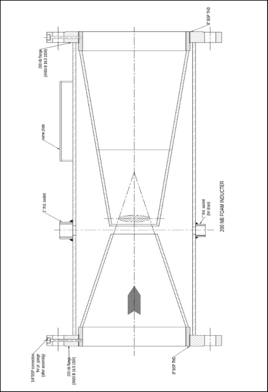
| Inductor size | A | B, mm | C, mm |
|---|---|---|---|
| 65 NB | 1" BSP (F) | 500 | 188 |
| 80 NB | 1" BSP (F) | 520 | 175 |
| 100 NB | 1" BSP (F) | 535 | 195 |
| 150 NB | 1" BSP (F) | 550 | 200 |
| 200 NB | 1" BSP (F) | 825 | 305 |
Approximate. A, B and C as marked on the datasheet drawing.
Construction & operation
Fixed inline foam inductors proportion foam concentrate in fixed installations with a constant flow: a simple, reliable way to induct concentrate into the water stream and deliver proportioned solution to the foam-making equipment.
Each inductor is designed and factory-calibrated for a set water pressure, flow and induction rate. A rise or fall in inlet pressure changes the flow, and with it the proportioning.
Available in three materials of construction, for flows of 75 to 3,500 L/min at inlet pressures of 6.4 to 12 bar.
System design
- Select and install the inductor in a hydraulically calculated system, within the permissible back pressure: at most 65% of the inductor inlet pressure.
- Performance is best above 8 bar (115 psi); the inlet pressure must be at least 6.5 bar.
- Mounted above the concentrate tank, the suction height from the tank bottom to the inductor centre must not exceed 1.75 m with AFFF, or 0.9 m with AR-AFFF 3/3%.
- Allow at least 600 mm of straight, unobstructed pipe at the inlet and the outlet.
- Supply and solution pipes must be no smaller than the inductor; the shut-off valve in the induction line must be a full-bore on-off valve.
Application
Suited to a single fixed discharge device. Not suitable for variable flow or pressure, or for sprinkler systems and other systems with many small-orifice outlets, where a blocked outlet raises the back pressure.
Installation and maintenance
Support the inductor firmly so no strain falls on it. A qualified, trained person must commission the system; after the first successful tests, train an authorised person to inspect and test it. Inspect regularly and test fully at least once a year, per NFPA or the local authority. Never shut the system or a valve for repair or test without a roving fire patrol in the protected area, and tell security and the alarm station so no false alarm is raised.
Where it is used
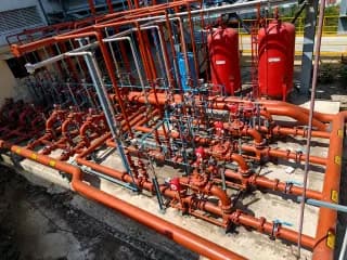
Part of these fire fighting solutions
Specified for these hazards
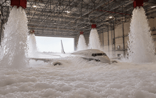 Aircraft HangarsHigh expansion foam and overhead systems to NFPA 409.
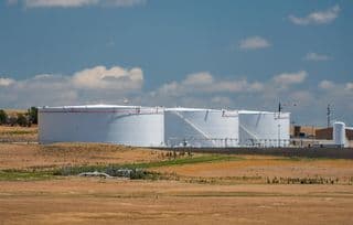 Fixed / Cone Roof TanksTop pourers and foam chambers discharging onto the liquid surface.
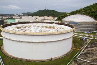 Floating Roof TanksRimseal fire and full-surface fire need different answers. Detection at the seal, foam at the roof.
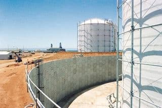 Tank Farm Bund / DykeFoam makers on the bund wall for spill fire in the containment area.
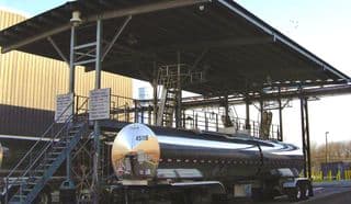 Truck & Rail GantryFoam and water spray over loading bays, with detection at the arms.
Downloads
- Product datasheetPDF ↓
Images · 2
Main view
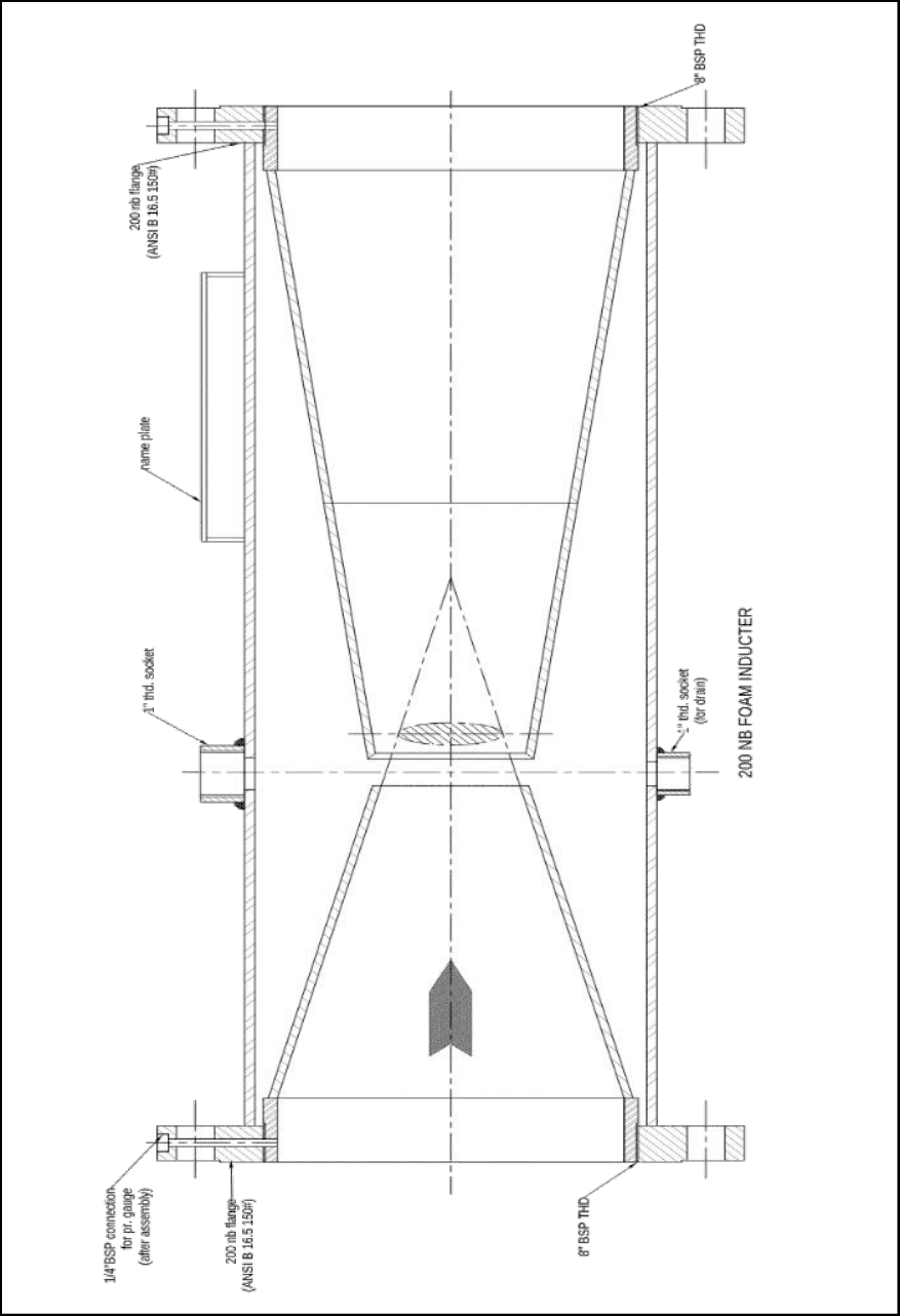
Isometric drawing
Related products

Send us a specification
Give us the duty, the medium and the standard. We reply with a selection and a price.